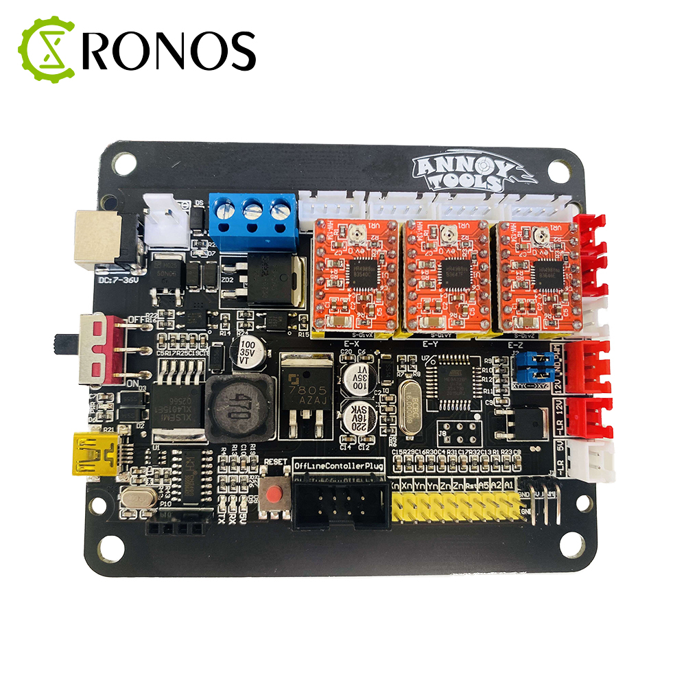

- #GRBL CONTROLLER AMPS DRIVERS#
- #GRBL CONTROLLER AMPS DRIVER#
- #GRBL CONTROLLER AMPS SOFTWARE#
- #GRBL CONTROLLER AMPS DOWNLOAD#
- #GRBL CONTROLLER AMPS MAC#
#GRBL CONTROLLER AMPS DOWNLOAD#
You can download the Universal Gcode Sender from this url. And the Universal G-Code sender makes this happen. Gcode is a set of X co-ordinate values that the machine needs to move along its axis.
#GRBL CONTROLLER AMPS SOFTWARE#
To do that you need to a software called as Universal Gcode Sender. Say if you want to move an inch then the number of steps determine if you are moving exact or not. These steps mean that every revolution of the stepper motor how far it moves. The second order of business is to set the X,Y and Z steps. Then hit the upload button to upload the Grbl to the Arduino. Select the right board and port from the Arduino menu. Once Arduino is restarted go to File > Examples > Grbl and select ‘grblupload’. Then we need to restart Arduino to see the library.
#GRBL CONTROLLER AMPS MAC#
In mac the libraries is at the following location ‘user/documents/Arduino/libraries/’. We need to copy this and place it in Arduino library. Once you unzip the folder you can see the folder named ‘grbl’. To download the GRBL please visit github at this url. Download and upload the grbl and then set the X,Y and Z step values. GRBL is an extensive library and if you read through the documentation you can learn a lot many things.īut for the sake of this tutorial we just need to know two things. Grbl as a language helps the computer communicate to the machine. The first order of business is to upload GRBL to the arduino. Now that the CNC Controller box is ready I can go ahead and switch it and connect the Arduino to my PC. Instead of glass this is a better choice. Then I can move everything inside the box and cover it on the top with a 4mm acrylic sheet. This kind of approach is slow but eliminates the changes to do mistakes. And I colour coded each line so there is no confusion. This of course included a lot of wires so I took my time to make one single line of connections at a time so I made no mistakes. Once all these components are attached to the box I was able to go ahead and do the connections based on the schematic diagram. I will explain the safety mechanism of these switch further down. This will allow air flow inside the controller box to cool the TB6600 stepper motor drivers.Īnd on the slanted face in the front I mounted an emergency stop switch, a power on switch and router switch. And in the front I cut a whole to mount two 40mm cooling fans. So I decided to 3D print some face plate with which I can hide the cut outs.Īt the back of the box I will have three connectors for the stepper motors, an AC power connector and a two pin plug for the router. But these holes are usually not perfect if you cut with a jig saw. So I have added links to them in the list above.Īt the front and the back I want to attach the connectors. The rest of the components used are a not absolutely necessary but its good if we could use them. So a 10amp or a 15amp power supply would be enough for a CNC machine of this size. If we do the math for three stepper motors we need about 9amps.
#GRBL CONTROLLER AMPS DRIVER#
Please check if your driver allows a wider range.
#GRBL CONTROLLER AMPS DRIVERS#
The version of TB6600 stepper motor drivers demanded that I used just 12v so I went with that. Power Supply:Ī power supply that can deliver a voltage between 12v and 24v is ideal. With Arduino Uno it is very easy to switch pins and get started with testing. But you can use a Arduino Nano too if you have one. I prefer to use Arduino Uno because it comes with a lot of safety features. In my case I went for the 16 micro stepping and set the driver to deliver around 3.0 – 3.2 amps of current. Because these come in different shapes and sizes. It may vary with the model of TB6600 stepper motor driver that you have. The first three switches manage the micro stepping and the last three switch manage the different current delivered.

This stepper motor driver has 6 switches on the sides and a tabular column printed on it. So the TB6600 stepper motor driver is perfect for this purpose. Since the power requirement of the stepper motor is around 3.0amps we need a stepper motor driver that can give at least 5amps. We will be using these values in the stepper motor driver. And the angle of rotation is 1.8 degree which is very common.

In my case the power requirement is 3.0amps. So its the amperes that you have to concentrate. Mostly they all work with 12v power and required different amperes. But the same rules apply to all the different sizes of the stepper motors. The stepper motors that I have used are Nema 23 stepper motors.


 0 kommentar(er)
